Modeling and characterization of a GTEM cell
The GTEM cell (Gigahertz Transverse ElectroMagnetic) is a tool widely used to generate in the laboratory known and homogeneous fields: in particular, it is suitable to emulate electric and magnetic fields of a plane wave (TEM mode) in a wide frequency band, ensuring good fields uniformity in the operating region. For the above features, TEM/GTEM cells are frequently used for the calibration of precision EM fields measurement instruments, as well as for electromagnetic compatibility (EMC) studies.
As part of a collaboration with RaiWay, thanks to the use of the COMSOL Multiphysics® simulation software, the electromagnetic behavior of an open GTEM cell existing at different operating frequencies has been analyzed. This study has allowed to identify the region inside the cell where the field is purely TEM. In addition, experimental values obtained using a real GTEM cell have been compared to the simulated results, providing a good agreement between them.
The GTEM cell (Gigahertz Transverse Electromagnetic) is a fundamental tool for the calibration of electric an magnetic field probes and for studies on electromagnetic compatibility (EMC), as it is able to emulate the effects of an incident plane wave (TEM mode) in a wide band of frequencies, ensuring uniformity of the field in the operating region.
A TEM cell is a transmission line in which the fundamental propagation mode is TEM. Such transmission line has a particular shape that makes it suitable to be able to house, in an area where the fields are homogeneous, devices on which to carry out laboratory tests . The cell consists of a power connector (port 1) in which the radio frequency signal is injected. A transmission line follows which is progressively dilated, obtaining the typical pyramidal shape. The impedance of the line is kept constant, leaving the proportions (section / distance) of the conductors unchanged. After a possible central section with a constant section, a further progressive reduction of the section follows, symmetrical to the first. The resulting transmission line is finally terminated (port 2) on a resistive load equal to the impedance of the line, in order to avoid standing waves.
In order to reduce the length of the device, which can reach several meters, it is possible to “truncate” the structure and introduce a broadband termination. The so-called GTEM cell is thus obtained. Termination is a delicate point of the GTEM cell: typically it is a resistor in combination with an absorber [1], which reduces the excitation of the TE and TM modes at high frequencies. The resonances of the non-transverse components of the field can be further reduced by considering an open GTEM cell [2], derived from a conventional GTEM cell by physically removing the side metal walls. However, this open structure inevitably becomes more sensitive to the influence of the external environment, due to the absence of shielding by the side metal walls.
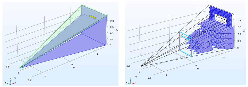
The electromagnetic behavior of the open GTEM cell at different operating frequencies (from 250 MHz to 1 GHz) was analyzed, creating an accurate finite-element model of the cell itself using the COMSOL Multiphysics software. The GTEM cell can be seen as an extension of a 50 ohm transmission line that expands in a pyramidal way, whose internal conductor is a thin metal layer (septum) and terminated by three series of anechoic pyramidal cones which, thanks to a partial reflection and transmission process, allow a drastic attenuation of the fields near the base of the GTEM cell [3,4]. This GTEM cell has an input impedance of 50 ?; in order to obtain more space inside, in the lower part, it has been designed asymmetrically, as two lines: the upper one, more compact, with 86.6 ? impedance; the lower one, with more space, with 116 ? impedance, in parallel with each other.
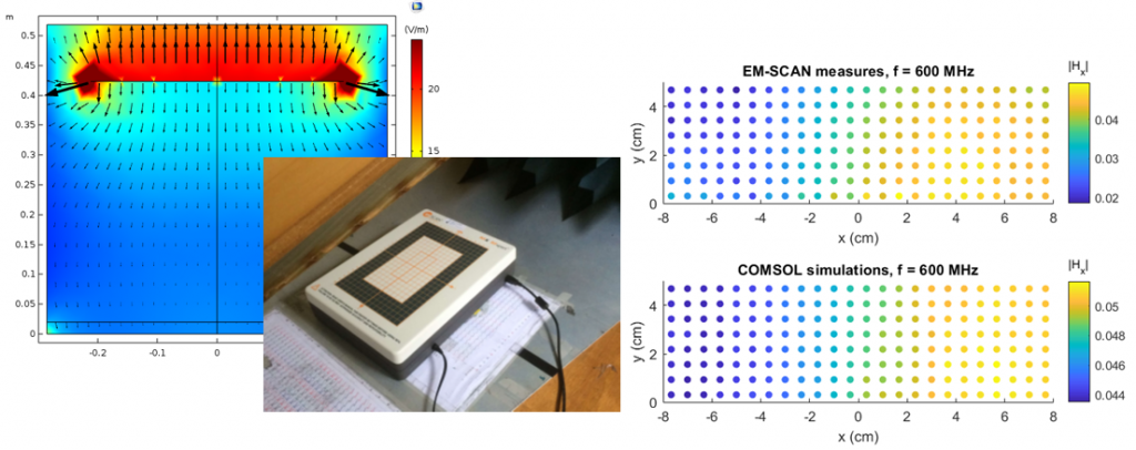
The simulations performed with COMSOL allowed to estimate the purity of the TEM mode, analyzing the relationship between the desired (transverse) field component and the other components; this allowed to identify the regions inside the cell where the propagation mode is purely TEM. Furthermore, it was possible to calculate the standing wave ratio (VSWR) on the power port, the value of which at different frequencies was validated by the experimental results obtained with the HP8753D vector network analyzer on the real GTEM cell. Finally, the magnetic field components evaluated with COMSOL in the GTEM internal test region were compared with a series of field measurements performed using a very near field scanner (EM-Scan RFX). This very compact bench-top instrument is usually used for the characterization of antennas in a laboratory environment with a broadband frequency coverage from 300 MHz to 6 GHz [5]. The RFX scanner performs a very-near-field mapping of the magnetic field and, in conventional use, provides, by calculation, the far field diagrams of the antenna. In this less conventional application, it allowed a rapid mapping of the tangential components of the magnetic field. The comparison between experimental measurements and simulation results provided a good agreement in terms of field uniformity.
More information
Authors:
Assunta De Vita, Rossella Gaffoglio, Bruno Sacco
Collaborations:
RaiWay, Quality, Security & Environment
References
[1] D. Konigstein and D. Hansen, “A New Family of TEM-cells with Enlarged Bandwidth and Optimized Working Volume”, Proceedings of the 7th International Zurich Symposium on Electromagnetic Compatibility, 127-130, Zurich (1987).
[2] R. Rambousky and H. Garbe, “Analysis of Open TEM-Waveguide Structures”, Ultra-Wideband, Short-Pulse Electromagnetics 10, 49-58, Springer, New York (2014).
[3] M. Bozzetti, et al., “Characterization of a GTEM cell designed for the SAR evaluation in in vitro experiments”, PIER Symposium 2004, Pisa.
[4] W.-T. Shay, W.-P. Hong, R.-R. Lao and J.-H. Tarng, “Design Methodology and Performance Evaluation of a Tapered Cell”, IEEE Trans. Instrum. Meas., vol. 62, no. 6, pp. 1821-27, 2013.
[5] EM-Scan-RFX2-Datasheet, Calgary, Canada.